Forum Replies Created
-
AuthorPosts
-
TweedBassmanMemberQuote:

The low pass filter on the POG is way too nice to not be able to control it with an expression pedal and have some moog flavour, aint it? I thought so, thus with the precious help of my friend electritabs I did that mod which includes putting jack for the exp.pedal in the front left corner, moving the LP slider at the back due to limited space inside the chassis and adding a toggle switch at the back next to the moved slider in order to be able to choose if the exp.pedal or the slider are functioning.
I use it with this great little switcher that my friend JAM made for me (check his pedals jampedals.com). Its a switcher that allows me to move the POG instantly between the first (where it should be when used as octaver) and last (when used just as a filter) in the pedal chain.
did you use this at all?
TweedBassmanMemberworks perfectly! With the footswitch you can set the expression pedal to a certain point, set the fader to another point, and footswitch between the two LPF settings. If you have a fast foot you can get some great warbly sounds, and with other effects going on being able to sweep the LPF with your foot has a huge effect on delays and reverbs afterwards, and you can control the harshness on the fly, a big problem when using dirt pedals with the POG. It’s cool.
I can’t wait to modulate it. Only thing missing is an LED indicator, but that’s just more wires. gah.
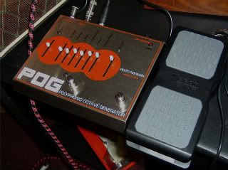
TweedBassmanMemberFinal product:
TweedBassmanMemberStep 10: Re-assembly
Before you put the board back in it’s home, you’ll need to re-solder the LED wires (remember, red on the outside!) and re-solder the power connections. Refer to the beginning of this if you need to look at the wiring, but don’t mess it up!
Next, take those 3 labeled fader wires and bend them so they are right next to the new footswitch hole.
Now that the power and LED are back, take that circuit board with 10 things flopping all around it and put it back on the posts and screw it down. The rest is pretty self explanatory, place the input and output jacks back in place (don’t swap them!) and place your TRS jack in your new hole. Here’s the layout there (output jack is orange one wire):
Nowwww… install the 3PDT in that new hole. You’ll have the 3 labeled wires from the fader poking out, solder them to the switch in this way:
Top fader lug: Lower right corner
Middle lug: Middle lower
Bottom fader lug: Lower left cornerRe-install the main footswitch. Re-install the LPF switch. Your finished guts should look like this:
Now, put the over back on, put the fader tips back on, and enjoy!
Remember, if there is no pedal plugged in, and the footswitch is in the EXP PDL position, it will be full filtered, all bass. In regular mode, the fader should still work as before.
TweedBassmanMemberOK, so now we have a modified fader glued into the chassis (haha…), wires coming from the circuit board, and holes drilled. Time to put it all together.
Step 9: Switch and Jack wiring
So now we’re in the home stretch. You can probably figure out the rest and I’m sure you want to rush ahead but take you time.
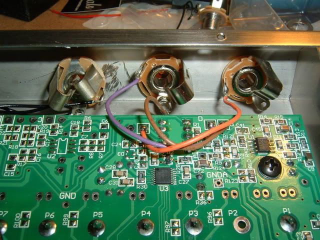
The 3 wires coming from the board (green wires here) need to be switched from a TRS jack, to the original fader. Here’s how:
Holding the switch with the lugs horizontal, the top wire goes to the right-center, the middle wire goes to the center, and the bottom wire goes to the left-center just like the pic.
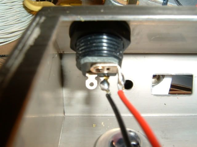
Now, grab your TRS Stereo jack. Solder 3 wires to it’s 3 lugs, long enough to reach across the entire pedal top to bottom. Here’s the wiring for that (sorry, no pic)
Tip: Right upper corner
Ring: Upper center
Sleeve: Left Upper cornerBy now, your J-B’d fader should be set up. Take the wires attached to it, and LABEL THEM. IMPORTANT. Label them with a small piece of tape, or colored pens, or whatever you can so you know which is the top, middle and bottom wire on the pot. I used a piece of electrical tape on the top wire, nothing in the middle and colored the end of the bottom wire with a sharpie.
Next, put a piece of electrical tape over the set fader. You want to cover up those wires coming from the bent lugs. They shouldn’t touch with the washers added, but this is just precautionary.
Now, re-assembly.
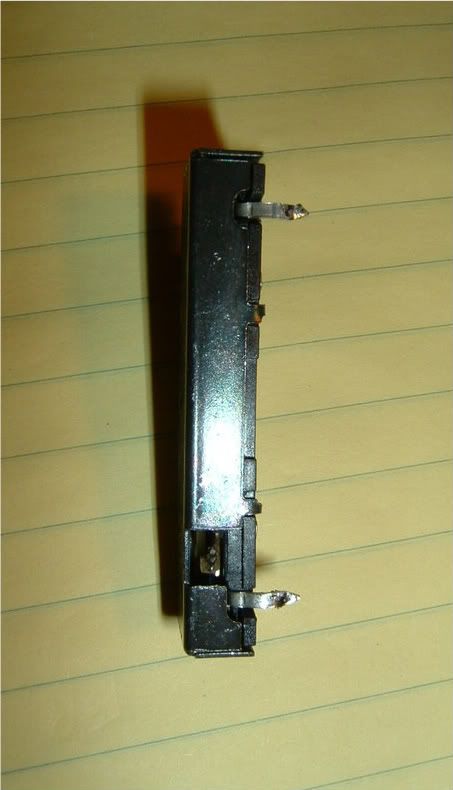
TweedBassmanMemberStep 8: Preparing and re-using the stock fader
If you installed the washers previously, now is the time to see what they are for. When you pull out the fader, it will have 3 lugs pointing up in the air. Remove any traces of excess solder. Now, you’ll want to CAREFULLY bend them down, all to the right with the fader’s two close lugs on the bottom. Don’t squish them flat, just give them a good 90 degree bend.
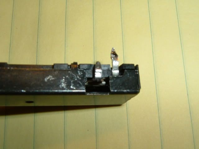
With the top and bottom lugs bent:
Here’s the middle lug bent over:
Now, with that done, you’ll need to strip off about 1/4″ from 3 pieces of wire, and bend each end into a hook. wrap the hook around a lug and solder in place. Do a nice tidy job if you can!
Here’s what you should have:
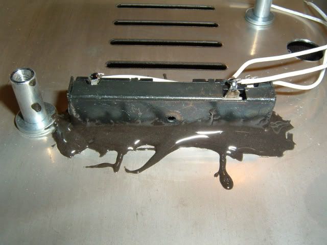
Now… how the hell do you mount the fader with no screws? J-B Weld! yeah i know… kinda make-shift to say the least. But, it feels really strong, strong enough that any force that could dis-lodge it would break the fader first!
You’ll need to do some prep. The fader itself has one side and both ends covered in metal, the rest is plastic. You;ll need to clean the sides of the fader casing with something that will cut through grease; I used Acetone.
Next, clean the underneath of the chassis with acetone, where the fader goes. be sure nOT to gloop any acetone through the hole onto the POG graphics, they’ll melt right off!!!!!
Now the tricky part. Read the instructions on the J-B, and mix it up. It sets up in 4 minutes, so be sure to do some dry runs first. You’ll have a few minutes to wiggle the fader after applying the ‘glue’. This is pretty tricky, very messy, but worked perfectly.
Gloop the J-B on the sides of the fader where it connects to the chassis. Give it a few wiggles so it sets in the cracks and spaces. When you are happy with the location and alignment, rest the chassis on that coffee cup with the fader tip out of the way so you don’t knock it out of place.
It will look something like this:
yeah, i know. looks horrible. Good thing no one sees it, and It’ll probably never come off. If it does, I’ll fess up and post it here. But, after letting it set up for 15 minutes, it’s SOLID. I was pretty surprised actually.
TweedBassmanMemberStep 6: Removing the fader.
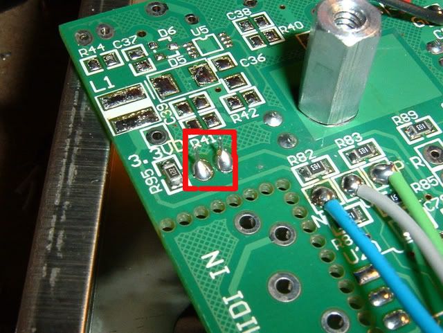
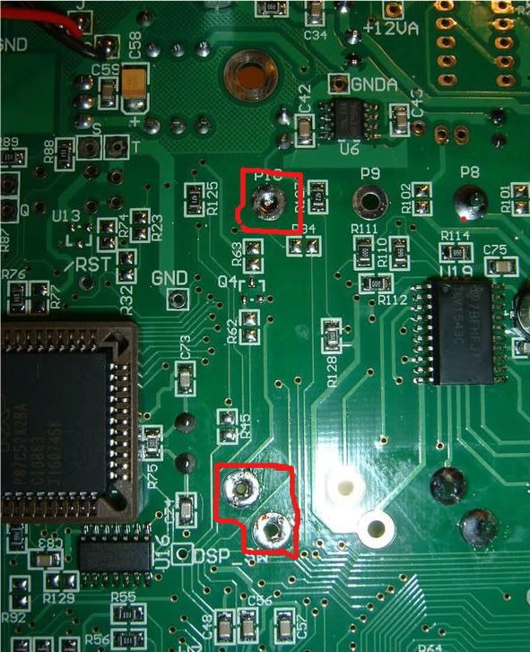
This in theory should be easy, but it’s not so take your time. There are 3 spots that you need to de-solder COMPLETELY, removing any trace of solder if possible. Even then, the fader will not pop out, and you’ll have to heat a section then wiggle, heat then wiggle, heat then wiggle… be EXTREMELY cautious so not to damage the circuit board or fader!
Here’s the 3 solder points you need to remove, in red:
Once you get that out, it’s time to decide if you will use the stock fader or go with a different 10KL pot located elsewhere.
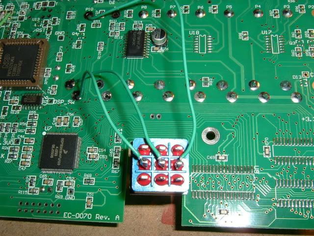
Step 7: Wiring the board
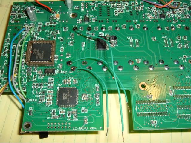
Wiring the board is easy. If you decide to do the easier Joe Perry Mod, simply wire in 3 wires to the 3 holes you just removed your fader from, like this:
Notice a few things: 1, there’s enough wire to reach that switch cutout. If you are going straight to a jack, make sure you put in enough wire to reach it. 2. The wires are put in the holes in certain directions to avoid any chance of slopping onto other traces on the board; notice the two bottom wires pointing out to the left to avoid the traces on the right.
Be sure to flip the board over and clip the excess wire ends off! VERY IMPORTANT!
Now… If you want to get rid of the fader, and have expression pedal control ONLY (that Perry mod), here’s the wiring:
Looking at the circuit board, with the switch cutouts on the bottom, the TOP point goes to the TIP of the TRS jack. The MIDDLE point on the bottom left goes to the RING, and the BOTTOM left point goes to the SLEEVE. The bottom point is ground, so an un-insulated jack will work.
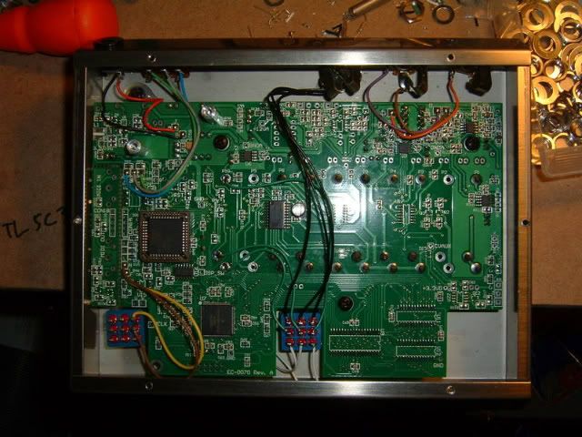
That’s the basic mod… now, let’s get crazy.TweedBassmanMemberStep 3: Board removal and drilling/prep.
With the LED and power connections removed, you can now carefully pop the entire circuit board out. BUT before you do…
If you’d like a neat factory looking 3PDT footswitch placement, mark the location now before removing the board. There is a nice perfect sized spot right in the center/bottom area. mark it with a sharpie… you want to mark it right in the middle, centered from left to right.
There are 3 screws holding the board in place; they are large black screws on the board. Remove them and put them in that cup. You may need to angle and wiggle the board, but now the whole thing should pop out.
Now, with the board out, use a small straightedge to line up the original footswitch hole with your sharpie marks. The idea is to have a X/Y location that matches the original switch but falls in that spot.
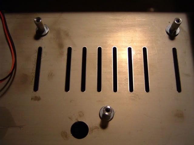
Your empty Chassis should look sorta like this:
Note: some work has been done to that pic. Here’s what needs to be done.
Step 4: Washers
On the face of the pedal there are 3 screws holding the circuit board stand-offs in place. loosen and remove those screws, and remove the stand offs inside the pedal. Immediately take 2 of your washers and put them UNDER the stand offs, and screw the stand offs back together. The purpose of adding height to the stand offs is to allow room for the modified fader. Add two washers under each one so it looks lke the photo above.
Step 5: Drilling
This is tough. these enclosures are harder to drill than the aluminum ones, so plan it out and take your time. I used a drill press. If you use a hand drill, BE CAREFUL because the enclosures are slippery and your bit could skirt across.
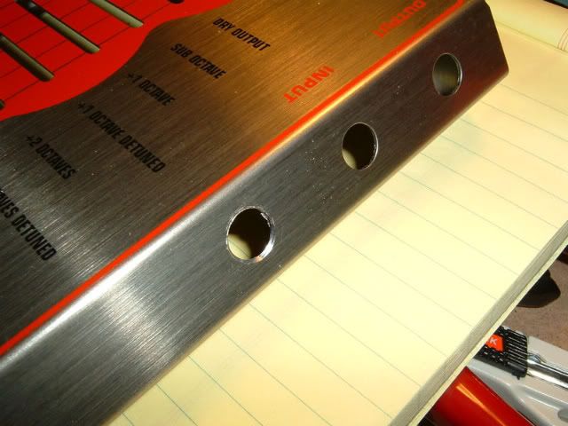
First, drill the EXP out. I put it evenly spaced next to the in and out jacks, it looks nice here.
I found that the best way to drill that weird angled piece was to place a piece of 1/2″ MDF under the surface being drilled. it has to be about 4″ x6 or 7″ so that you can place it flat on your drill press.
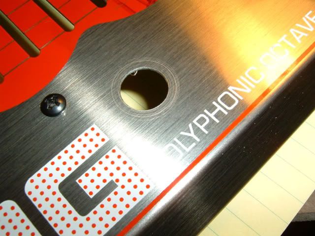
After that, drill your 1/2″ hole for the footswitch or your 3PDT toggle. You may want to tap up the face of the pedal and rill it from underneath were you lined up your hole location with the circuit board.
You’ll notice in the next pic there are some swirl marks on the outside. Avoid that my drilling a little then cleaning your bit; as the metal shaves off, it sticks to the bit and goes for a ride. It’s covered by the switch though.
After you have all your holes drilled, clean up the edges with a dremel if need be.
TweedBassmanMemberOK here we go. EHX POG Low Pass filter Expression out mod.
First, you’ll need to have a good understanding of basic guitar pedal electronics and DIY stuff… knowing terms like 3PDT, pot wiper, de-soldering skills and tools, etc. It’s not recommended for your first mod.
Next… be careful! This can be a tricky mod, and it is a digital pedal that has very delicate and sensitive components inside. Be wary of too much heat during soldering/de-soldering, and be careful not to make any dumb mistakes like touching a wire with the iron by accident.
Then, you’ll need to decide how far you want to go with this modification. This tutorial discusses an ‘all out’ modification, which retains the factory LPF fader and keeps the pedal factory stock looking, which I prefer.
The first version, which I’ll call the “Joe Perry” LPF mod, simply removes the LPF fader entirely and replaces it with a stereo output jack, connected to an expression pedal. In this mod, you will NEED to have an expression pedal hooked up all the time, it replaces the fader. This is the easiest version to do, but very limiting. If you disconnect the expression pedal (and have no switching invloved) the LPF will turn all the way down, turning the sound into mud.
You could also wire up a stereo switching jack, but that would involve either a replacement pot or fader modification (both discussed next).
2nd version is wiring a 3PDT (either toggle or footswitch) to switch the LPF fader from expression out to a new potentiometer. This pot would replace the fader when the expression pedal is not being used. This is a good alternative if you think the ‘all out’ version looks like a pain (it is…) but it means having a non-matching knob somewhere on the pedal.
3rd is the version in this tutorial, which modifies the existing fader. This involves a lot of non-electrical work that you may not want to get involved in. I recommend reading the whole thing and deciding if it’s worth the time and effort to do. Taking notes and pictures along the way, this mod took me about 3 hours (with a trip to the hardware store).
If you decide to do the first or second version of the mod, just follow along here and you should be able to figure it out. I’ll try to remember to post extra notes along the way.
PARTS AND TOOLS:
Expression pedal that is 10k-12k. I used the M-Audio one. ONLY a 10k-12k exp pedal will work.
Stereo TRS 1/4″ jack
3PDT switch, either footswitch or toggle. I’d recommend footswitch for a factory look and live usage.
De-soldering tools. A vacuum is preferable, but whatever gets the job done. The fader is tough to get out, be prepared.
Wire. to keep yourself sane I’d recommend 3 colors. I used 24 gauge, 7 strand pre-bonded wire.
Usual DIY tools… Needle nose pliers, pencil tips, wire strippers, soldering iron, drill with step bit or drill press, wrenches, etc.
Washers. You’ll need 6 small (i used #8 size) metal washers IF you want to reuse the stock fader.
J-B Kwik 2 part epoxy; again, if you want to re-use the fader. This is available at home depot for about $4.Patience.
Step One: Dis-assembly and chassis prep.
Unplug unit. duh.
Remove the white plastic tips from the faders. Put them in a coffee cup or similar (there will be a lot of parts later, don’t skip this.) Carefully remove the nut holding the footswitch on, put in cup. Remove Nuts and washers holding on In/Out jacks. Cup. Remove screws holding LPF switch. Put ’em in the Cup. Remove 6 screws holding back plate on. Cup ’em.
Take a look inside. Carefully remove the in/out jacks from there spots, move the LPF switch, and footswitch.
Step two: De-soldering begins
You will need to completely de-solder and remove the following:
The LED connection. You’ll be removing the black and red wires going to the status LED, de-soldered from the circuit board. Here’s the spots:
be sure to note the locations! Refer back here to put them back in. the red wire is closest to the outside of the board.
Next, you’ll need to de-solder the power input jack. It helps to wiggle out the circuit board to get a better look. I removed the wires from the jack itself, but you may want to remove the wires from the board instead. Here’s the pic, note where the red and black go (VERY IMPORTANT! when re-connecting, refer to here to get the polarity correct! Don’t fry your pedal!)
to be continued….
TweedBassmanMembercool just finished. man, what a pain!
i’ll get the how-to up soon.
TweedBassmanMemberthat’s a good idea too… but i do a lot of ‘table top’ usage also so i’d like to have the fader or a real knob on hand.
i think i figured it out. is it cool to post the pics and how-to here?
TweedBassmanMembertough call. i would need to drill 3 additional holes… EXP out, replacement pot, and the 3PDT switch. the 3PDT could just be a footswitch, and the EXP out, well that’s the point; but a big goofy knob replacing the fader would look ridiculous.
unless i could find a panel mount fader that fit perfectly and had a low enough profile to not touch the board… i doubt it. i guess i could hot glue the fader in place.
if i end up doing it i’ll post pics and how-to here.
ahhh screw it i’m gonna do it. i think i figured out the best way. stay tuned.
oh btw admins/mods… can we post modifications here?
TweedBassmanMemberQuote:Just like I suspected, you need to totally bypass the original pot for it to work. Also, the reason the slider was giving incorrect readings IN the unit is because the other parts create resistance and lead to false readings, the only real way of testing resistors and variable resistors is to remove them entirely…as you’ve found out.BTW, are you tweedbassman from pennypedals?
thanks man… yeah that’s me. i’ve never encountered weird readings and such with analog circuitry, digital stuff scares me..
you should have seen my face the first time the POG turned off while hacking it.the final piece to the puzzle is a picture of Joe Perry’s pedalboard. the LPF exp out was always rumored to have been done on his POG but no other information was around. knowing what i do now, you can see in his old board pics the LPF fader is gone from his POG; completely replaced by an expression pedal.
there sure are a lot of unused connections inside a POG… CV… MIDI…
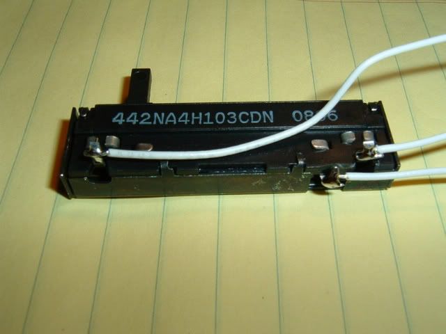
TweedBassmanMemberalright. here’s the deal.
i removed the 10K linear fader. there are two lugs on the right, one on the left; the left one is the wiper.
replacing the fader with a 10k linear pot worked perfectly, and it seems the bottom lug on the fader (closest to the footswitch) is ground; aka, wired up very much like an analog LPF or tone control on a guitar.
or, so i thought.
in a standard analog LPF, you can set the pot to full resistance (in this case, 10k) and add a second pot in parallel ‘tacked’ onto the 3 lugs. the second pot can offer a less resistive path to ground and will take over when turned down.
unfortunately, this is not the case on the POG. the fader must be controlling a digital message, because wired in this fashion the replacement pot does nothing until the very end of the travel, then it shuts the pedal off.
so, the correct answer is: the fader must be completely bypassed, and switched out with a 3PDT switch wired to a stereo jack. luckily, the 3rd lug is ground so a non-isolated stereo jack ill work fine.
now, it’s just a matter of mechanics. the easiest thing to do would be to replace the fader with a knob and rotary pot. without the lugs of the fader soldered to the circuit board (remember they have to be isolated for the exp out to work), the fader would just flop around inside. no good.
so, is the mod worth adding a secondary knob (and removing the fader) and drilling two holes? hmmmm/
TweedBassmanMemberOK i couldn’t wait for you guys.
took out the fader, it’s 10K linear.
alright. here’s the deal.
-
AuthorPosts

")