Forum Replies Created
-
AuthorPosts
-
ScruffieMember
Okay, hopefully this diagram helps, this is for the EHX positive tip supply.
I’ve added a 1N4002 diode on the drawing too, if you add this in if you make a mistake with the wiring or plug in a negative tip supply in the future by mistake the circuit will be protected.

You can remove the 3 original transformer wires as you aren’t using it anymore.
ScruffieMemberPost a photo and i’ll see if I can see any wiring errors.
ScruffieMemberI agree replacing all the electros & tants is a reasonable course of action, they’re nearly 40 years old already so saves you a job down the line but I hate to think of the PCB and active parts being replaced for no reason and ruining its originality, while it probably is one of the opamps you could easily pin point which one and then keep it as stock as possible, especially as those old boards can be a bit flimsy so replacing that many parts might take its toll.
If you take the voltages of all the opamps and post them i’ll be able to tell you where the problem is, you don’t have to remove anything to do that.
Page 3 here has a readable and correct schematic to help (albeit with an additional output booster circuit and vibe switch) http://lectric-fx.com/wp-content/uploads/2016/07/Bloodstone_V.1.1.pdf
ScruffieMemberReplacing all the parts blindly isn’t the best way to debug, do you have access to a multimeter? You can pick one up very cheaply.
Then if you post up voltages it should be possible to see where your issue stems from.
ScruffieMemberHi Paul,
No a buzzer wont be any good, the point of the audio probe is that you can hear exactly what is happening to the signal at different points in the circuit, so if you probed the input transistor base and there was nothing or a very weak signal you could assume there’s a bad connection from the input jack or a short somewhere and if you probed the second transistors collector and there was no boosting happening you’d know the issue was between the transistors etc.
And yes the 9V battery needs to be installed and the circuit switched on with some kind of signal being put through the circuit (strumming a guitar, a CD player or whatever) when probing.
ScruffieMemberI meant you’ll have to wire the lugs on this the opposite way to the other adapter as the EHX adapter is center positive instead of negative.

So where it says to board – you’d wire it to board +
ScruffieMemberOkay, next step then is an audio probe, here is a guide to building one and how to use one, it’s quite simple and should get to the bottom of where the problem is.
http://www.diystompboxes.com/wiki/index.php?title=Debugging
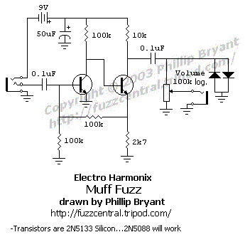
And the schematic to work from;

Test at the base and collector of each transistor and describe what you hear.
ScruffieMemberThat should be fine, you’d just have to wire the DC jack the opposite way as it’s a positive tip.
ScruffieMemberI thought the good vibes was optical based, not BBD?
ScruffieMemberI mean a standard pedal power supply that supplies 18V from the wall voltage, one like this would work https://www.thomann.de/gb/pigtronix_18v_power_supply.htm
And then you’d have to fit one of these to where the cable used to come from and solder it to the board in the right place.
http://www.taydaelectronics.com/hardware/dc-power/dc-power-jack-2-1mm-enclosed-frame-with-switch.htmlScruffieMemberQuote:Quote:…an 18V DC pedal supply to power it…Why 18V?
There is an 78L15 regulator on board which regulates the voltage to 15V but it needs some extra voltage (about 1.7V if I recall correctly) to do its job and 18V is a fairly standard supply voltage that meets that criteria.
September 3, 2016 at 6:51 pm in reply to: Hot Tubes arrived with low voltage and it’s awesome #121966ScruffieMemberYou can measure pin 8 of the dual opamp in each one, that will tell you what voltage the circuit is seeing.
 ScruffieMember
Try powering just the B9 on its own and see if the noise remains.
September 3, 2016 at 1:11 pm in reply to: Hot Tubes arrived with low voltage and it’s awesome #121962ScruffieMemberA dimmer LED doesn’t necessarily mean the circuit is getting less power, it may just be that there is some variation (due to unavoidable component tolerances or perhaps there was a minor circuit revision) that are giving the circuits a different sound.
The only way to be certain one is getting lower voltage for whatever reason is to purchase a cheap multimeter and measure the voltage, if that does turn out to be the case, you can either purchase or make a voltage starve circuit.
But, I would guess it’s just the tolerances making the two sound a bit different, that’s not to say starving the voltage wont get it closer in sound regardless, but it might not.
ScruffieMemberHow are you powering it? The B9 needs an isolated supply, sounds like you might have it on a chain.
-
AuthorPosts


