Forum Replies Created
-
AuthorPosts
-
April 19, 2020 at 10:39 pm in reply to: Questions about vintage Memory Man Solid State Echo Chorus repair w/pics #126009ScruffieMember
No sound doesn’t necessarily mean a power supply problem, no, but as you tested your supply and had no voltage you’ve answered one question yourself
 this unit does require power for bypass.
AC doesn’t have a polarity, but DC does, but hopefully the rectifier diodes will have provided some polarity protection.
ScruffieMemberWell, unless there’s some form of over voltage protection (possible, but there’s no schematic to say with any certainty) I would suspect it’s super dead… I doubt the electro caps are rated to take 50V, op amps generally have a 36V max rating, even most standard transistors aren’t rated to take that much.
But as flanders said, a photo might help, I think I spot a ICL7660 in there so perhaps it has zener protection which will probably be quite clearly blackened if the supply was in there for any period of time.
ScruffieMemberThere’s not really a thing as ‘too many buffers’ your signal doesn’t get over buffered.
True bypass is useful with specific pedals like vintage fuzzes that rely on direct guitar/pedal interaction but I can’t see anything in your chain that would meet that criteria and you already have a buffer first in chain (TU2) so the point is moot.
So if you like the pedal, go for it.
There’s plenty of articles on the topic if you’d like to learn more, here’s the first that came up http://www.roland.co.uk/blog/the-truth-about-true-bypass-and-buffered-guitar-pedals/
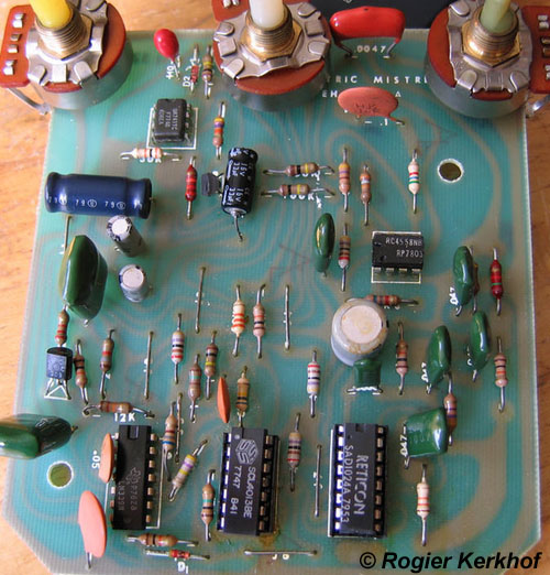
ScruffieMemberSo the circuit board looks like this and there’s nothing visibly changed?


[img]http://www.metzgerralf.de/elekt/stomp/mistress/images/em_v4/v4_3.JPG[/img]
If so, it’s possible the 10uF cap from the output buffer has gone bad.
ScruffieMemberQuote:its packed away in a road case right now.. What would a photo tell you?The specific version & if there’s any factory or prior user mods.
ScruffieMemberWell, definitely a very early unit, October chips, December schematic, January/February ’78 production? and in nice condition for its age too.
Does it have any components added to the back of the circuit board? If not, you can probably conclude it’s a first run.
ScruffieMemberSo it is (not sure why mine has a later date, looks identical apart from post dated annotations) still, the very end of ’77… I can’t imagine they rushed them out before new years eve


They did use old pots as you know which does seem the much more likely answer.
As for the #3, some of them had stuff scribbled on the boards, no idea what it means but that’s not the only unit I’ve seen with numbering.
Sometimes IC’s had dating, post a photo of the component side too.
ScruffieMemberI’ve never heard of anyone complain of a mistress giving a volume jump rather than drop!
Can you provide some photos of the board?
ScruffieMemberThe factory schematic for the Deluxe Electric Mistress is dated November ’78 so it seems quite unlikely there were earlier units, especially that much earlier.
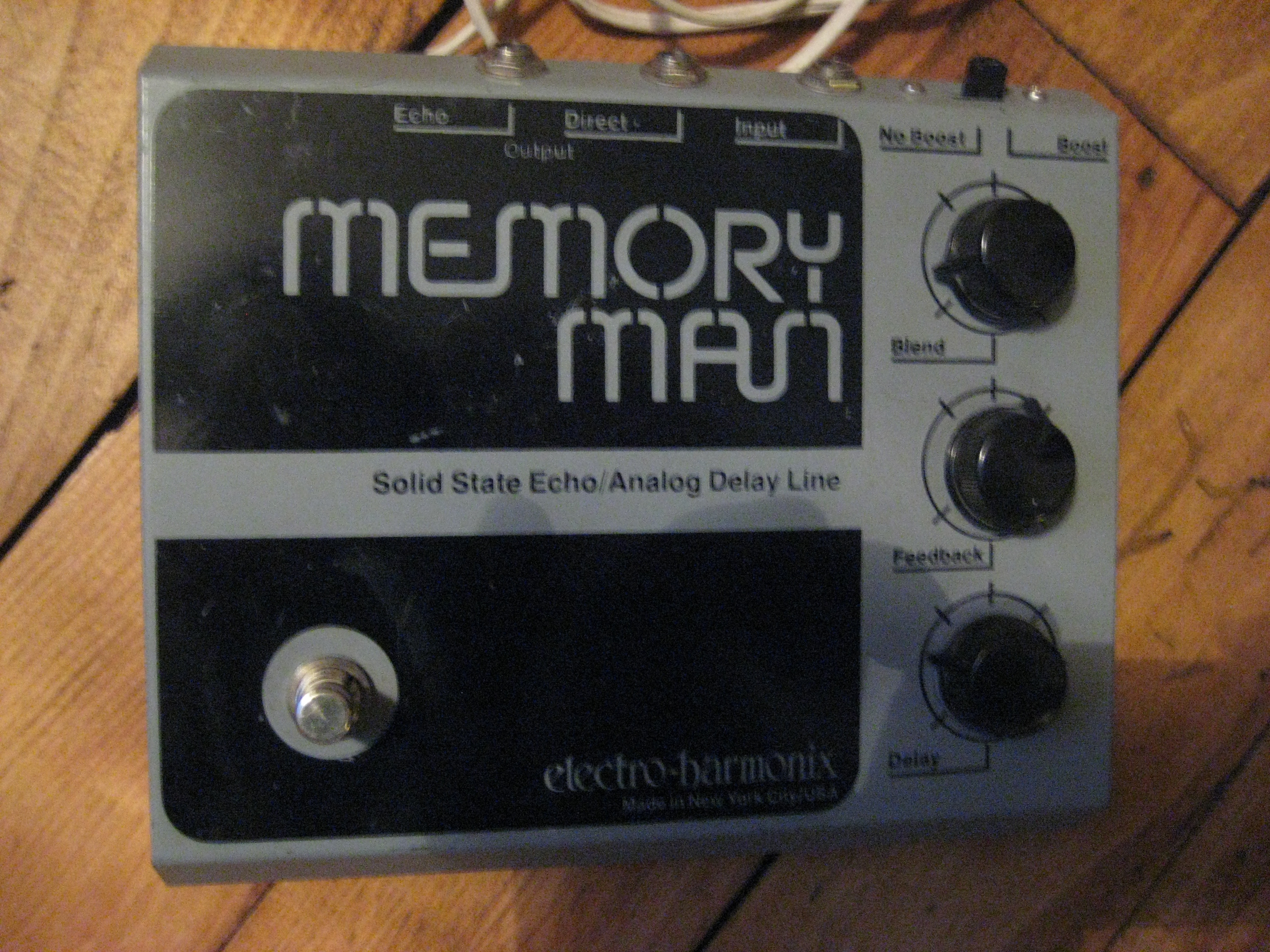
ScruffieMemberIt’s an early (prototype?) model of the first iteration of the memory man delay (distinguished by its unique enclosure) I worked on one in the hands of a collector a few years back (this is only the second or third I’ve seen) IIRC it’s very similar circuit wise to the production model solid state echo with boost switch apart from an OTA based voltage reference circuit that was later omitted


The schematic for that model without the OTA circuit dates it to January ’78 (same date as the 4 knob deluxe version and titled ‘economy memory man’) so this was likely from late ’77.
ScruffieMemberNo, the greenies and circular (and that red square one) are mylar and ceramic non polarized capacitors, they very rarely go bad and should be left alone.
Just those 2 blue and 2 brown in the centre as you say and the electrolytic are the barrel shaped capacitors.
You MUST make note of the polarity of these capacitors when replacing them (I usually take a couple of photos and then use a sharpie to mark the board before removing them) the stripe on the barrels indicates the negative and on the tantalums they should have a + symbol.
Also you need to make sure the voltage rating on the new capacitors is equal to or greater than the original you’re replacing.
ScruffieMemberWithout checking the schematic I can already tell you, your LM324 should have some moving voltages on it and the voltages on half your 571 are way off.
My suggestion would be to start by just replacing all the electrolytic and tantalum capacitors first of all (unless you want to individually test them, but I wouldn’t personally bother), they’re probably 40 years old by now and they’re the most common issue I find in repairing old EHX.
Good news is that your clock and SAD voltages look good.
ScruffieMemberWhere are you located? In the US try The EH Man, in the EU, I can take a peek.
ScruffieMember1980 V5 Op Amp model, turn it on and it either works or it doesn’t, you don’t need to replace anything if the pedal works and as for screws, 4-40 cross pan head.
ScruffieMemberVoltage readings are needed to give any kind of educated answer, plus testing the slide switch for continuity.
But it will likely be one of 4 things, the switch itself, a bad solder joint, the 4u7 cap connected to pin 3 of the 1458 or the 1458 its self.
-
AuthorPosts