Forum Replies Created
-
AuthorPosts
-
baeheezelmauthParticipant
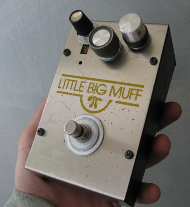
the old brown paint just melted off when i wiped it down with rubbing alcohol…
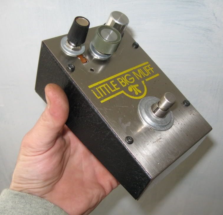
I gasped at first, but the yellow was unaffected.there is not alot of room in there for more stuff so I had to squeeze those other pots in…
and I have a bin full of salvaged knobs so Im gonna let the owner pic some to taste.baeheezelmauthParticipantthanks so much for the terrific help…
I dont even own a guitar, so i have only tested this with a func.generator..
but all systems seem go…
from seeing all kinds of big muff schematics.. i decided to get adventurous
and see if i could turn this into a big-big muff by adding 100k pots to the
obvious areas on the board…
I removed the jumper and resistor from the distortion area and added one
and simply replaced the tone switch with a pot…so does that sound right?
here are some ext. pics


 baeheezelmauthParticipant
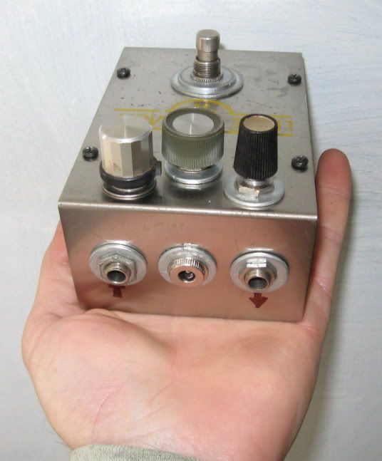
alright, so using this pic, L to R jacks and lugs…

correct me where im wrong…
1-“INST” 1/4in in jack
a- to “IN” pad on board
b- to neg (-) batt lead
c- to ground pad / 3rd pot-lug trace2- AC power jack (pos-inside, neg-outside)
d- to “AC” pad on board
e- to pos (+) batt lead3- “AMP” 1/4in out jack
f- to stomp switch lug “i”and then
-stomp switch..-single-lug side
g- to trace leading to “OUT” on board-double-lug side
h- to “IN” pad on board
i- to “AMP” out jack lug “f”THANKS!!
baeheezelmauthParticipantvery good.
and it looks like my stomp switch is missing a wire.
it has one lug on one side going to a trace connected to the “out” pad on the board…
and on the double-lug side of the stomp switch it has only one, going to the “amp” out-jack
the other is missing…
does that go to the final lug on the 1/4in input jack?THANKS!!!!
baeheezelmauthParticipantnice! thanks-
so- I’ve got that one… the “in” wire.
and so the other 2 points on the 1/4in input jack.. are
power switching?
i am missing those too:(I can see where the center (+?) on the power input goes to the “AC” pad..
where is that red (-?) going?are the red and black going to a battery lead?
im grasping to figure this out for a friend… he is stoked at the
chance to use this again after 14 ? years!thanks alot for your help!!
baeheezelmauthParticipantso, I have found these pics that have helped a little…

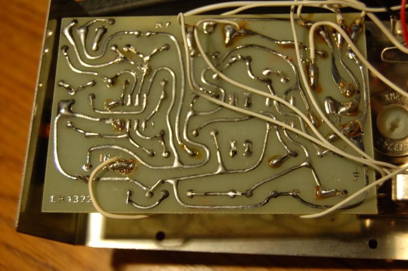


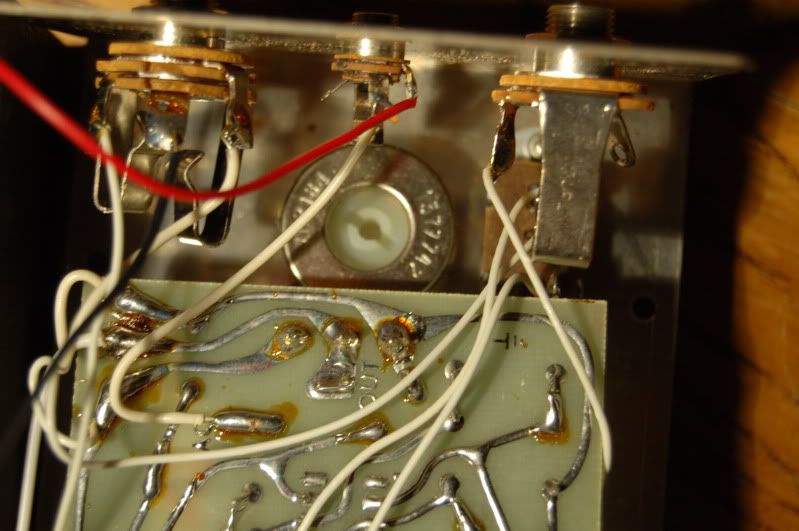
the first is just a hair away from working for me, but the all-white wire color scheme
is a bit frustrating:)I think i now only need to see where all the input wires go.
the bottom one would work if the wires were color coded or numbered… -
AuthorPosts
