

Home › Forums › Help/Technical Questions › wiring a small stone usa ver.1 for true bypass.
- This topic has 11 replies, 6 voices, and was last updated 10 years, 7 months ago by thebends9.
-
AuthorPosts
-
January 24, 2010 at 7:04 am #79749spiketheguitaristMember
hi all,
my footswitch for my ver.1 small stone just went out so i figured i would try to wire it true bypass. i found useful wiring diagrams here in the forums but i dont know which wires are the fx input and the fx output on my circut board. i dont have a digital camera to take a pic of my board but i found a pic of one with the exact same layout as mine. here is the link
http://www.pedalarea.com/small_stone.htm#
its the very center picture right under the version 1 bio. any help would be greatly appreciated.
January 25, 2010 at 2:23 am #106779Ned FlandersModeratorThe effect input and output wires are: Input – the one coming straight from the input jack to the PCB,this also goes to the switch but nevermind that. Output- the one coming from the PCB to the switch.
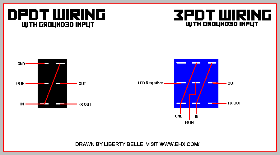
Follow this true bypass diagram or your SS will oscillate like mad in bypass mode if the color switch is up and it doesn’t have grounded input: (use the one on the left and don’t bother with an LED)
http://i1016.photobucket.com/albums/af286/fenderamerica/Pedal Schematics/MYTBSWITCH.png
“GND” is ground, so use ground on one of the jacks for this.
January 25, 2010 at 3:51 am #106780spiketheguitaristMemberQuote:The effect input and output wires are: Input – the one coming straight from the input jack to the PCB,this also goes to the switch but nevermind that. Output- the one coming from the PCB to the switch.Follow this true bypass diagram or your SS will oscillate like mad in bypass mode if the color switch is up and it doesn’t have grounded input: (use the one on the left and don’t bother with an LED)
http://i1016.photobucket.com/albums/af286/fenderamerica/Pedal Schematics/MYTBSWITCH.png
“GND” is ground, so use ground on one of the jacks for this.
thx liberty. im looking at the pedal now and it looks a bit different than you described. i have 3 wires connected to the input jack- one (white) thats connected to the footswitch, another (orange) thats connected to the color switch, and another (white 2) thats connected to the pcb, white and orange are both soldered to the same lug of the input jack (tip). white 2 is soldered onto another lug (sleeve). does this make a difference? also, this is the switch i got…
http://www.phonekings.com/ebay/auctiongif/carling.jpg
i got this one because its the same shape as the original spdt switch. but is the lug order still the same as on a standard dpdt? i actually used one of your other wiring diagrams you posted in a earlier thread but couldnt get it to work (the alternate one at the bottom of pic).
https://www.ehx.com/?ACT=25&fid=5&aid=190_uqGHAKBEiK2Xk4PSDcyo&board_id=1
i assumed the lug order was still the same and that white 2 (sleeve) was the fx input so i unsoldered it from the sleeve lug and wired it to the switch. but when i hooked it up it worked in bypass but i could hear the phaser coming through like you described (and i did ground it to the input jack ground where the 9v battery ground was soldered). when i hit the switch it would basically mute my guitar…..i could barely hear it if i cranked my amp up. so yeah something is still not right. this is definitely starting to become a pickle
 January 25, 2010 at 5:53 am #106781Ned FlandersModerator
so does it work in bypass AND on mode? nevermind the oscillation, we can fix that.
Nevermind the color switch for now . There should be four wires going to the PCB, one is the battery, ones is ground, one is effect output and one is effect input, try and locate them.
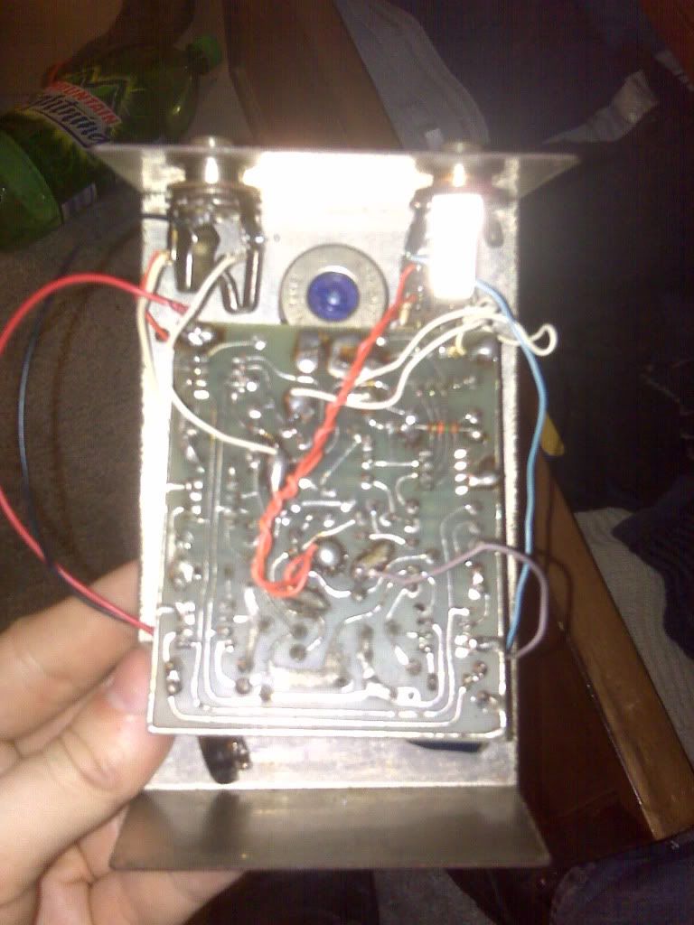
January 25, 2010 at 7:57 am #106784spiketheguitaristMemberit works in bypass. but oscillation is heard faintly. when effect is on my signal is faintly heard if i turn my amp up. now if i unhook the battery and plug in the signal doesn’t change at all when i hit the switch. which makes me think that it is getting power. this is what it was sort of doing with the original switch. and when i would play around with the switch i could get it to eventually work. but maybe this isnt a switching problem. anyways i did have a chance to take a pic of it. here it is.
January 25, 2010 at 8:18 am #106786Ned FlandersModeratorOut of three wires on there I cant tell which is in/out as my SS is a 79 and a different layout than this.
If I had the pedal i could work it out easy enough but without it I cant.
Just wait till the EH man shows up, he’ll know straight away.January 25, 2010 at 8:54 am #106788spiketheguitaristMemberQuote:Out of three wires on there I cant tell which is in/out as my SS is a 79 and a different layout than this.
If I had the pedal i could work it out easy enough but without it I cant.
Just wait till the EH man shows up, he’ll know straight away.EH man? Now im curious
February 6, 2010 at 10:53 pm #107183The EH ManModeratorTook me a while but here’s a diagram. There’s a wire going to the Color switch which is the effect input.
March 29, 2010 at 12:03 am #108859spiketheguitaristMemberHey Guys,
I know its been awhile since i posted about my true bypass question. I just now got the free time to try to rewire the thing. Well here is what happened.
I wired it according to the diagram liberty belle showed me and it worked…..until i tried hit the switch to put it into bypass and then nothing. it muted my guitar signal. so then i tried the diagram the eh man posted and that worked, but i could hear the phaser in bypass (as liberty belle said this would happen with that type of wiring). anyway im curious if anyone knows why my signal is being muted when i put it into bypass. i checked all my solder points and everything seems to be connected correctly. so once again any help will be appreciated.
August 27, 2010 at 8:04 am #111116devnulljpParticipantHey, Can I cut in? I have a similar issue trying to resurrect a v1 Small Stone. I can’t make out where the wires go from Ron’s diagram…
The one marked pink — does it go to the bottom left lug of the Color switch? Does it share the lug with the wire connecting to the input jack?
I’m presuming the one marked green replaces the green one in the photo?
I wired it up that way to see, and what I get is a kinda motorboat/pulse at high rate that I can turn the speed down but no phasing. It’s more intense with the color switch up…
Any ideas? (I get bypass signal OK).Thanks
EDIT: Using Liberty’s 3PDT diagram, is this right?
Is there still a wire from the input jack to the color switch?EDIT2: I just wired it up as above and I also get nothing in bypass. But with the effect on, all I get is motorboating … a pulse overlaid on the clean guitar signal. Something’s not right over and above the true bypass but my old switch was knackered so it had to be done. I guess I don’t have the switch wired up right? (Is there really two jumpers?)
October 18, 2010 at 4:10 pm #112029MartyMcFlyMemberDo these same instructions apply to a green Sovtek Small Stone?
May 25, 2014 at 4:42 pm #119998thebends9MemberBringing back an old thread.
Has anyone completed this successfully, and if so, can you please provide a picture of the switch wiring.
I picked up one recentky that had an issue with the original DPDT switch. I have now removed it but I cannot get mine to work using the above diagrams (on a DPDT or 3PDT) switch…
Thanks in advance.
-
AuthorPosts

")


- You must be logged in to reply to this topic.

