- This topic has 1 reply, 2 voices, and was last updated 8 years, 10 months ago by .
Viewing 2 posts - 1 through 2 (of 2 total)
Viewing 2 posts - 1 through 2 (of 2 total)
- You must be logged in to reply to this topic.
Home › Forums › Vintage EHX › Vintage SwitchBlade Wiring Picture
I have an Electro-Harmonix switch blade channel selector I bought back in the 70’s. The issue I have is it was modified in the 70’s, to be just an on/off foot switch. I want to return it back to it’s original functionality. However I need a wiring diagram. I might be able to get by with a close-up picture of the wiring. Is that something someone can provide? I would really appreciate it. Please let me know. Thanks.
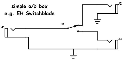
If you can use a DVM, you can have it rewired in no time. It is likely a simple SPDT footswitch, although some ‘fancy’ versions can have a DPDT to ground out the ‘unused’ output, reducing noise. If you’re keeping it, and want to get even fancier, a 3PDT switch can be put in, and the 3rd pole can add an LED with say a 470Ω resistor. Here is a simple drawing.
J1 is your input. J2 is output A and J3 is output B. S1 is the footswitch. There will be a common lug, and a meter will show which lug is active during pressing the switch. I hope this helps.
