

Home › Forums › Help/Technical Questions › Restoring Green Big Muff Pi (early 90’s)
- This topic has 5 replies, 2 voices, and was last updated 14 years, 8 months ago by Captain Pickguard.
-
AuthorPosts
-
March 28, 2010 at 8:18 pm #80095Captain PickguardParticipant
Hi – new user here. I am a guitar builder and I build and repair tube amps. I’m hoping to learn a little about pedals and get some advice.
I got a request to repair a big muff pi (Russian – tall skinny letters) from one of my customers. Of course I want to try to help him out. I replaced a jack and replaced the set-screw on one of the knobs. Everything’s good except the foot-switch is missing the nut and the top. I would either like to get a nut for the original foot-switch or replace it. I’m not trying to mod the switch for bypass, just get it back to functioning.
Looking at the switch it has the obvious six connections and then two more unusual connections to metal strips that extend down into the switch housing. What are those connections? And if can’t get the nut what can I use to replace this switch? Or can I get the nut? The thread count seems unusual.
March 29, 2010 at 12:49 am #108860Ned FlandersModeratorYou cant get replacement parts for it from any stores.
Them two tabs are not part of the switching and are irrelevant.
Also, the pinout of the sovtek switches is not the same as standard DPDT switches.It doesn’t go like this: (so wiring it as per normal DPDT will result in a pedal that will not work)
14
25
36So you’ll have to use a 3PDT and wire like this diagram below.
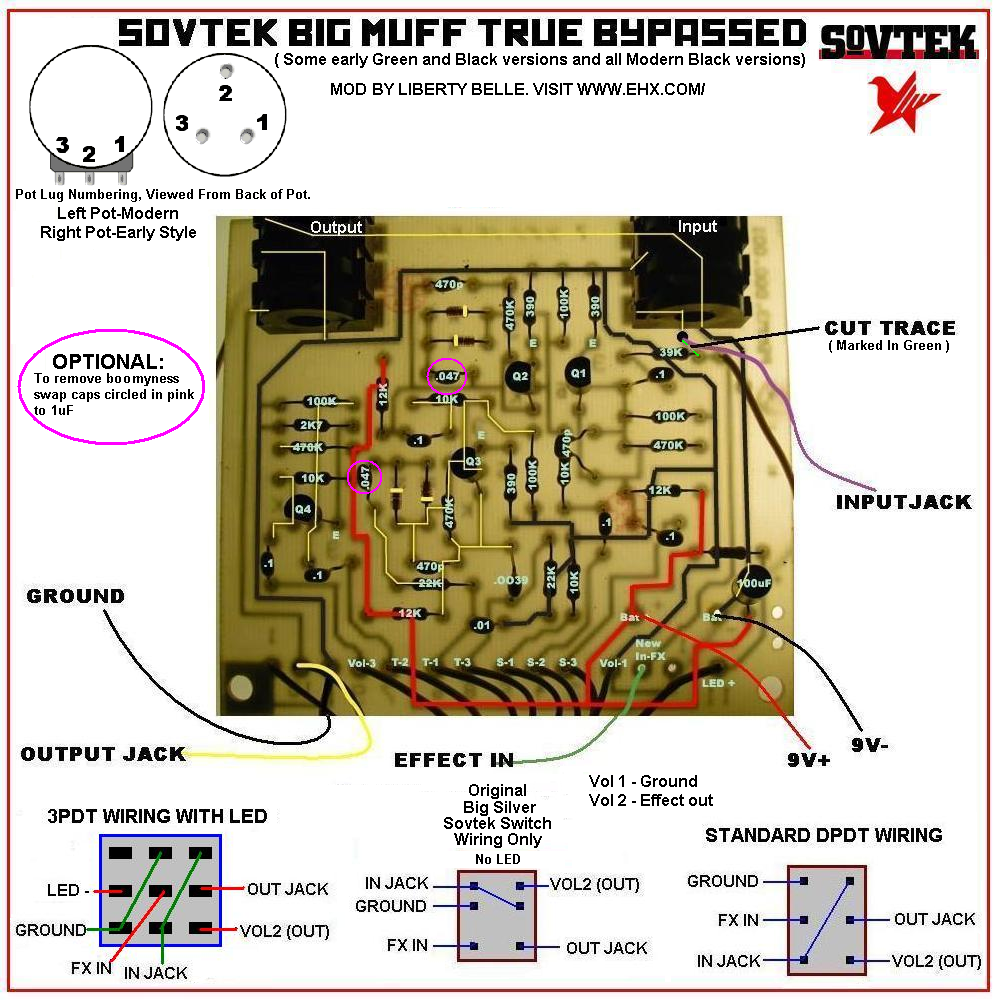
Don’t forget to cut the trace between input jack and effect input.
This diagram provides all the information you need to true bypass it. You’ll need two big washers that you use to mount the new smaller switch the the inside chassis plate as the hole is obviously too big to mount a 3PDT.
http://i1016.photobucket.com/albums/af286/fenderamerica/Pedal Schematics/CCCPBIGMUFFTBD.png
Essentially, you are doing this to it and the end result should look like this:
 March 29, 2010 at 3:45 am #108864Captain PickguardParticipant
Thanks for the diagram. I anticipated not being able to get the nut (or the missing cap on top of the switch). Mine doesn’t look quite like the diagram, but it points me in the right direction. Those connections that are not part of the switch have a resistor across them and go to the LED.
Let me get a new switch and see how far I get. I’m sure I can trace the wires if I get confused. It’s funny, but tube amps seem a lot less complicated than pedals.
March 29, 2010 at 5:25 am #108866Captain PickguardParticipantOK, I took a longer look and I am hesitating because this pedal looks significantly different than what’s in the diagram. I also tried checking the continuity of the connections to the existing switch and they do not appear to match the connections of the “Original Big Silver Sovtek Switch” in the diagram. Is that the wrong way to check the wires? The resistor across the switch that goes to the LED still has me puzzled. Why is it connected to the switch that way?
Here’s pics:
http://i286.photobucket.com/albums/ll88/rdelange/BigMuffPi/BigMuffPi003.jpg
http://i286.photobucket.com/albums/ll88/rdelange/BigMuffPi/BigMuffPi004.jpg
I do not want to modify this pedal for true bypass. I just want to replace the switch. How would I wire a 3PDT as a simple replacement?
March 29, 2010 at 12:51 pm #108870Ned FlandersModeratorMy diagram of the sovtek switch is 100% verified, I drew it from one of my big muffs myself when I true bypassed them. So I don’t know what your doing or whatever. If you’re not getting any continuity the switch is fucked. if you are and its different then you are doing something wrong.
Yeah, I posted the wrong diagram sorry. here’s the correct one:
http://i1016.photobucket.com/albums/af286/fenderamerica/Pedal Schematics/SOVTEKTRUEBYPASSED.pngJust use the first diagram I gave you for the switch wiring as this ones for the sovtek switch true bypass.
March 30, 2010 at 3:46 am #108898Captain PickguardParticipantLB, I’m not questioning your diagram. I’m questioning my ability to check the wires. I’m pretty new with pedal mods.
I have stated that I didn’t want to wire it for true bypass, BUT your diagrams have emboldened me to do it and I do appreciate your effort to help.
Just so I have a clearer idea of what I’m doing, can you look over my summary to make sure I didn’t miss anything?
Here’s what I got so far:
1) wire the new switch (per diagram)
2) cut the trace
3) run a new wire from the input to the switchIs that all there is?
-
AuthorPosts


- You must be logged in to reply to this topic.

